Continuing where we left off with optimizing chilled water flow, this article is taking a look at cooling tower control for the same large shopping mall in the DC area. When EES showed up for the first time on site at the chiller/tower plant, the tower control was terrible. The control was “tuned” by the client’s local HVAC tech, and it went from off, to 90%, to off, every few minutes.
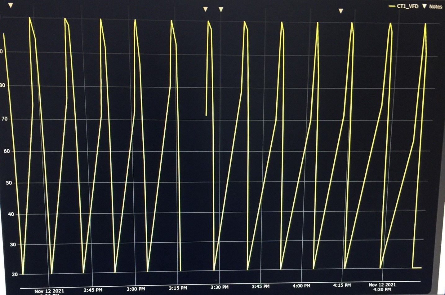
Not only did this wreck havoc on the condenser water supply temperature, and subsequently the loading of the chiller, it also drastically shortened the life of the fan motors themselves.
Step one was to tune the loop to be more stable. We removed the antiquated control system from the plant area and replaced them with state-of-the-art ABB CBXi-8R8-H controllers.
The loop controls the tower fan speed to make a setpoint of condenser supply water.
This worked through a season with the operator deciding how many towers to have running at a given time.
Step two was to automate how many towers to run, based on load. In a situation with too few towers, more energy is required to spin the fan and eventually the setpoint will be eluded. The problem with many fans is that, at minimum speed, the fan is making the water too cold, which causes the chiller to trip out. This allows the fans to cycle and maintain a temperature to satisfy the chillers.
Fans power is proportional to the cube of the speed, so cutting a fan speed in half (1/2) uses 1/8 (½ x ½ x ½) the power. Balancing the number of fans running with the control at the low end is a seemingly simple task. It takes time to tune when the staging should occur and is based on the physical setup of the tower/chiller plant. It is not as simple as the end result might hint at. This particular site had some defective valves. This caused us to reprogram the sequences to maintain temperature. The valves are awaiting replacement and they will then be added to the control sequence.
In the above picture, the green line is the outside air temperature, which impacts both the tower and the building load. The cyan (light blue) curve is tower #1 and the dark blue is tower #2.
The goal is to keep the purple line straight, or nearly straight, at the setpoint of 73 degrees. At about 1:00 PM, the system went from needing one tower to needing two. The resulting kW went from (right side y-axis) 9 to 2 times 2.5 or 5 kW. There was a brief temperature drop as the system adjusted the fan speed with the additional tower running.
As the temperature dropped, the building load (not shown) followed. At about 7:00 PM, the system reduced the number of towers to one in anticipation of the cooler evening. The temperature briefly spiked upward while the system ramped up the remaining tower.
As the evening progressed, one tower was more than enough to maintain temperature through the overnight hours. The fan was running at about 11% full speed, which is the minimum set for it. It is important to set a minimum on the VFD or else the fan may run too slowly to cool its own motor, causing it to overheat and fail prematurely. If we had left both fans running at minimum, we would have overcooled the condenser water.
In conclusion, engineers think about more than just “working” equipment. They take into account equipment longevity, energy savings, and leveling out fluctuations to make the downstream equipment serviced run more efficiently as well. We also completed the documentation package that the client had, which had many gaps.
The overall condenser water one-line is shown below.